

HOW TO CREATE SKETCHES IN NX
In NX, you can create the sketch of a feature by using two methods: Direct Sketch and Sketch in Task Environment.
Direct Sketch: In Direct Sketch, you can create sketch in the Modeling environment directly by invoking the sketch tools available in the Direct Sketch group.
Sketch in Task Environment: In this method, you need to invoke the sketching environment by choosing the Sketch in Task Environment tool from the Curve tab of the Ribbon.
Direct Sketch (Sketches in the Modeling Environment):
To Invoke Direct Sketch: Home > Direct Sketch > Sketch
We know that the base feature or the first feature in the design is always a sketch-based feature. The profiles of the sketch-based features are defined by using a sketch. Therefore, to create the base feature, first you need to create a sketch.
You can create a sketch in NX by using the datum coordinate system plane (XC-YC, YC-ZC, or XC-ZC), any reference plane.
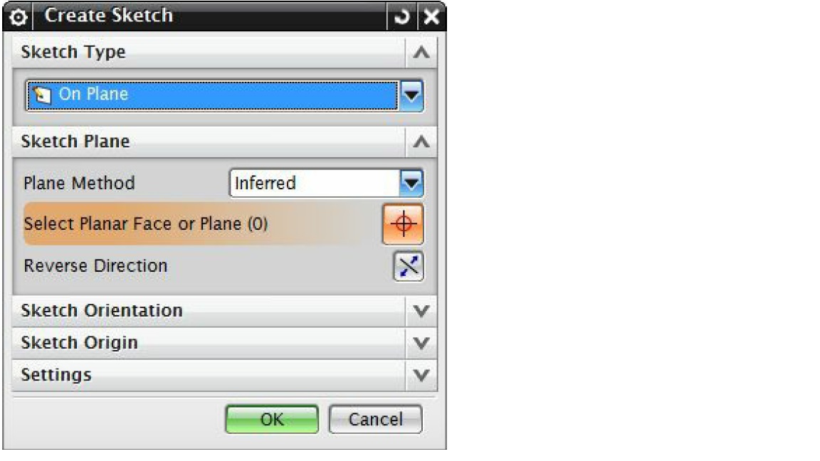
To create a sketch in the Modeling environment, you can use the sketching tools available in the Sketch Curve gallery of the Direct Sketch group and create sketch directly in the modeling environment itself. Please note that by default, in the Modeling environment, all the sketching tools are not available. To get the full access of sketching tools in the modeling environment, choose the Sketch tool from the Direct Sketch group from the Home tab, the Create Sketch dialog box will be displayed. You will be prompted to select an object for the sketch plane or select a sketch axis to have better orientation. Please note that the Direct Sketch group will be available only when you are in the Modeling environment or Sheet Metal environment. The various options in the rollouts of the Create Sketch dialog box are:
- On Plane: This option is used to specify the existing plane, face, or datum coordinate system plane as the base sketching plane.
- On Path: This option is used to determine the sketching plane on the current path. The temporary sketch plane will be generated perpendicular to the path.
Depending upon the option Selection from the drop-down list, the Create Sketch dialog box will be modified.
Important term and definitions in NX
On Plane Options
By default, the required parameters related to the On Plane option will be displayed in the Create Sketch dialog box.
Sketch Plane Rollout:
The following are the various options used in this rollout to specify the sketch plane by different methods. The options in this rollout are as follows:
- Plane Method: The Plane Method drop-down list provides various options to select the sketch plane. Following are some of these options:
- Inferred: “Inferred” option is default selection in the Plane Method drop-down list. It allows you to pick the current plane and planar faces.
- Existing Plane: Select “Existing Plane” option to determine the existing plane or face as the sketch plane.
- Create Plane: Select “Create Plane” option to construct a new datum plane and use it as the current sketch plane. When you select this option, the Specify Plane area is displayed in the Sketch Plane rollout.
- Create Datum CSYS: Create Datum CSYS is used to create a new datum coordinate system.
- Reverse Direction: As Name suggests, the Reverse Direction button is used to reverse the direction of the sketching plane.
Sketch Orientation Rollout:
The Sketch Orientation rollout options are used to specify the horizontal or vertical reference for the sketch. The sketching plane gets orientated according to the specified references. The options in this rollout are:
- Reference: Select the required option i.e. Horizontal or Vertical from the Reference selection list to define the reference for the sketch.
- Select Reference: We can specify the horizontal or vertical reference by selecting the existing planar face, edge, datum axis, or datum plane with Select Reference button. The sketching plane gets oriented according to the specified reference. The horizontal and vertical constraints will be added to the sketch with respect to the specified reference direction.
- Reverse Direction: The Reverse Direction button in the Sketch Orientation rollout is used to reverse the direction of reference specified (horizontal or vertical).
Describes the applications of NX Basic
Sketch Origin Rollout:
Following are the Sketch Origin rollout options that are used to specify the origin point of the sketch. The options in this rollout are:
- Specify Point: Specify Point option is used to select the origin point of the sketch plane. We can make any specific point in the sketch plane as the origin of the sketch by selecting a point on the sketch plane. You can also use the Point Dialog button to create or locate a point in the Sketching area.
Settings Rollout:
Following are some of the rollout options that are used to specify additional settings while selecting a sketch.
- Create Intermediate Datum CSYS: This checkbox is always checked marked by default. Due to this, an intermediate datum coordinate system is created and is associated to the sketch plane. Also, when you delete the sketch plane, sketch will not be deleted.
- Associative Origin: This checkbox is used to associate the origin point of the sketch to the sketch plane. This checkbox is available only when the Create Intermediate Datum CSYS checkbox is selected.
- Project Work Part Origin: This checkbox is used to create the sketch in absolute world coordinate system.
We will more post on CAD Tool–>Siemens NX in upcoming days.
Kindly provide your valuable comment on below Comment section and also have you any question kindly ask to ASK QUESTION in FORUM . Our Team will try to provide the best workaround.
Kindly subscribe your Email-Id at (http://globalplm.com/) and drop any suggestion/queries to (globalplm2@gmail.com).