

Teamcenter consists of two types of Architecture.
2-Tier Teamcenter Architecture
4 -Tier Teamcenter Architecture
Kindly see below Actual system representation of Architecture.
System Level Diagram of 2-Tier Architecture
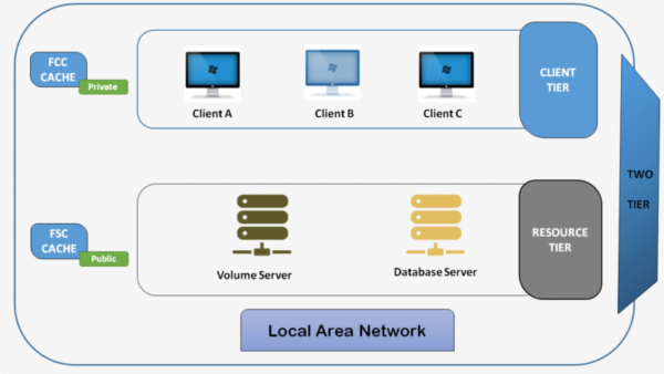
Client Tier: Rich Client & CAD Applications , Visualization , Teamcenter Server executable.
Resource Tier: Database & Volumes

System Level Diagram of 4-Tier Architecture
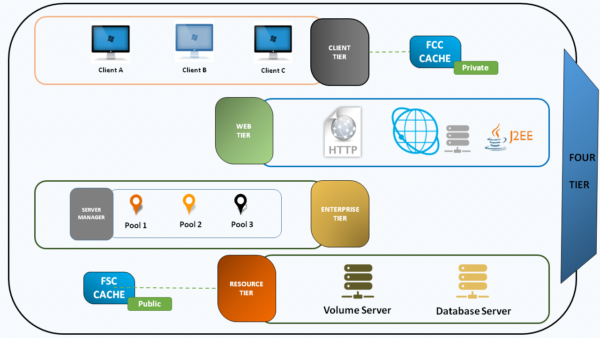
Client Tier: Rich Client & CAD Applications, Visualization
Web Tier: J2EE or .NET web-based application server
Enterprise Tier: Pool of Server Processes
Resource Tier: Database & Volumes
 Comparison of 2-Tier and 4-Tier
2-Tier |
4-Tier |
It contains
|
It contains
|
| On opening one can find TAO window present. | On opening one can find TAO window NOT present.
|
| It supports Rich client interface. | It supports Rich client and Thin client interface. |
| It is recommended to work on LAN Environment.
|
It is recommended to work on high-latency WANs. |
| It Requires low latency (Ping time) between client tier and the resource tier. | Any client not present on the same LAN as the Web and Enterprise tiers should be deployed as 4-tier. |
| For Latencies under 5ms it is preferred | For Latencies up to 300ms, it is preferred. |
–
We will more post on PLM Tutorial–>Teamcenter in upcoming days.
Kindly provide your valuable comment on below Comment section and also have you any question kindly ask to a ASK QUESTION in FORUM . OurTeam will try to provide the best workaround.
Kindly subscribe your Email-Id at (http://globalplm.com/) and drop any suggestion/queries to ([email protected]).